Jump to content
  • PROGLIDE - Home Built Composite F5J 3.8m Glider - Update


    ThermalBoy

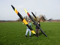
    It's been over a year since I (Colin Paddon) and Kevin Beale first posted details of our home built and designed 3.8m composite F5J glider, PROGLIDE. This update brings us up to date with the project.

    It’s all very well designing and building your own competition plane but its not worth a lot if it turns out to be lacking in performance compared to the professionally manufactured gliders that it will be flying against. There seems to be a general misconception that home built F5J competition gliders are in some way inferior to the professional commercial offerings in terms of their flying performance.  Straight away lets dispel this myth. The prototype PROGLIDE in its first full year of competition use won three UK F5J league competitions and finished 2nd in the 2016 National UK F5J league with an overall score of 99.06%. Myth dispelled.

    The only downside of designing and producing your own composite F5J plane is the time and effort it takes to do. If we paid ourselves 50p per hour for all the time we have put into this project we still wouldn’t be able to afford to buy them! It’s a complete labour of love in every way but the sense of achievement makes it all worthwhile.  A quick look at the web gallery that accompanies this article will give you some idea of the time and effort that has gone into achieving our original goal which was that it must be economical to build, use techniques that anyone with reasonable building skills can learn/do and most importantly have as good a flight performance as the commercial offerings.  Achieving the 100% perfect finish compared to the hollow moulded professionally produced planes was not a high priority. We were only interested in its flight performance and were happy to accept a good finish as opposed to a perfect one.

    proglide_f5j_update_29.JPG proglide_f5j_update_30.JPG

    During the development period we worked in parallel on different areas of design/construction. For example I decided that I wanted to be able to split the fuselage in half for ease of air transport which meant that the elevator and rudder servo’s were both enclosed within the tailplane mount pod with the boom being secured to the Fuselage Pod spigot by two carbon tubes that could be removed and the boom slid off. Ditto the fin/rudder assembly. Kevin worked on optimising his layout with the servos under the wing at first followed later by the elevator servo in the tailplane pod and the rudder servo under the wing. For his Fin/Rudder he went along a similar route that the Nan Xplorers use. Finding easy to do home build solutions to problems took time, effort and testing. 

    One of the things that several people asked us about was how we made the wing joiners. In the end it was so simple that I wondered why I hadn’t thought of it before. Buy yourself from HobbyKing a protruded 10x10mm square section carbon rod which comes with a 8mm dia hole all the way through it. Cut into required joiner lengths and angle the two inner end faces to the required angle. Roll up 40mm of unicarbon tows to achieve a tight fit inside the hole, wet out fully with epoxy and slide it half way into one half of the joiner and then the other. Put balsa caps down the hole so that it just very slightly compresses the central wet unicarbon and keeps them centrally located within the length of the joiner and then clamp into required position and allow to set. Result, pair of carbon joiners that weigh 23g total. The plane would be destroyed before the wing joiners broke. This technique wouldn’t be strong enough for F3J planes but more than adequate for our lesser stressed F5J models. Quick, cheap and foolproof with the ability to create any angle of joiners you require. Kevin went a different route by using straight solid round carbon rod which allowed him in our normal wing section to get the required dihedral tip angle he wanted. 
    All this problem solving sounds as if it was a PITA, and at times it felt that way,  but in reality we both enjoyed finding home build solutions to these challenges.

    The first two Proglide’s produced used cheap fibreglass cloth on the flying surfaces which enabled us to learn the required composite skills knowing that when it goes wrong (it will BTW!) that it hadn’t cost the earth in materials. However, the aim was always to eventually use Carboline which is a fantastic cloth but it’s not without good reason that it’s called “Black Gold”, its very expensive but gives a strength to weight ratio that is unbeatable for our purpose. 

    The early fibreglass skinned versions of PROGLIDE achieved RTF weights of between 1450-1580g, ie still reasonably light for a full house 3.8m electric plane. With each new plane we tried different lay-up’s, build techniques and incorporated various detail design changes along the way. Lots of time was expended in producing test pieces during this period to prove the viability of what we were doing. We had failures along the way on pieces that we felt sure would work well but turned out not to be of the standard we were seeking. Amongst the various failures though we managed to have some light bulb moments which were always welcomed! One such moment came when we started to investigate how to achieve repeatable 100% success with shaped inflation bladders in the moulding of the fuselage pod in order to minimise the weight.  After quite a few failures it turned out that a fine tipped soldering iron and Recycled black rubbish bags (yes really) worked brilliantly. The variable air pressure for this task was handled by a £50 EBay airbrush compressor which had a small air reservoir tank.  After trying various layups, like most of the professional manufacturers, we have now settled on using all carbon for the fuse pods. 

    Another light bulb moment came in regard to hinging the flying surfaces. At first we used silicon hinges which did work but were relatively heavy and difficult to get perfect every time. We later moved to using Diamond tape for the hinge along with Microfibre tape on the inner faces of the foam. (Microfibre tape sticks like the proverbial to raw pink foam). This resulted in strong, lightweight quick to apply, field serviceable (if required) hinges that were very free in their movement. They have turned out to be every bit as good as silicon hinges and in many respects far better. 

    After building a few Proglides we felt confident enough to move onto using Carboline. We also decided at this point that we would again take advantage of having two of us involved. Kevin’s first Carboline PROGLIDE was to use our normal wing section whilst mine was going to use one of the new F5J Syner ultra-thin wing sections. We had hoped to use a friend’s CNC foam cutter for this new prototype wing but unfortunately he moved house just at the wrong time and we all know how much time they take up to get sorted out. So, yet more wing /spar templates to make! Using such a thin wing section on a 3.8m wing brought with it a host of new structural problems to overcome and additionally neither of us was totally convinced that these Ultra-Thin wing sections were the right way to go for F5J.  

    Kevin progressed quickly on his first Carboline build as we now knew exactly how and what to do. He made no attempt to get this plane down to be a super lightweight and used standard sized servo’s with a heavy motor/ESC/battery in the fit out. Even so the finished RTF weight came in at just under 1440g. He estimated that had he used lightweight equipment the finished RTF weight would have been easily under 1300g. The project was moving in the right direction.  After flying it Kevin liked his PROGLIDE so much that he immediately decided to press on and make a full on lightweight  Carboline version. This ultra lightweight PROGLIDE, which he seemed to put together in record time, came in at 1280g. It fly’s superbly. 

    Meanwhile, it took me a while to iron out the new structural issues raised when building a 3.8m solid core ultra-lightweight thin section wing. Eventually though we were ready to proceed with the build. Did it go smoothly, of course not! Due to a stupid error on my part during the bagging up of the centre panel, I managed to ruin the entire panel. It was an expensive and time consuming mistake to make.  After the required amount of San Miguel I decided to build a new centre section straight away. I took this “opportunity” to try a different approach with the spar structure. The rest of the build thankfully went without a hitch. The plane RTF came in at 1245g using lightweight radio gear, 1000mah 3S Hv Lipo and a 85g direct drive motor. All that was needed now was to test fly it to see if it performed as well as we hoped it would. Following several test flying sessions we can report that its flight performance has exceeded all expectations. All preconceived negative thoughts on whether ultra-thin wing sections would work well for F5J have been dispelled. 

    In light of the successful flight testing of the first thin wing PROGLIDE we have decided to build a heavier windy weather version using the same thin wing section. In the meantime the Carboline Ultra light just tested can be ballasted to 1550g AUW which hopefully will be capable of handling a decent amount of wind (yet to be tested). But as we all know, here in the UK there’s times when you just need a heavy plane.

    For those that are interested in weights here they are.

    Part Finished Weight With Gear Installed Weight
    Carbon Fuse Pod 89g 135g
    Boom & Tailplane Mount 35g 55g
    Centre Panel 263g 333g
    Left Wing Tip 128g 150g
    Right Wing Tip 130g 152g
    Elevator 33g 35g
    Fin/Rudder/Tube 24g 24g
    Prop/Spinner/Motor   113g
    ESC   50g
    Other installed equipment   78g
    Total AU RTF Weight   1245g

    proglide_f5j_update_31.JPG

    In terms of airframe material costs, the fibreglass skinned versions come in at around £100-£130 and Carboline versions at £200-£250. Labour cost….well let’s not go there! Overall, somewhat cheaper for an equivalent commercially produced 3.8m F5J model at this kind of weight!

    So what next? We are confident that we can further reduce the overall weight with minor detail changes, improved lay-ups etc, but recognise that we are getting close to what can realistically be achieved in this regard with home building.

    A picture really does say a thousand words, so if you are interested in seeing how the PROGLIDE is constructed, the photo web gallery that accompanies this write up shows all. If you have any specific questions about the plane or its construction please feel free to ask on this thread.

    Colin Paddon/Kevin Beale

    Proglide-F5J.jpg

    • Like 3

    User Feedback

    Recommended Comments

    7 minutes ago, thermaldoctor said:

    Brilliant write up Col

    Neil

    That coming from you Neil is praise indeed. Thankyou.

    Colin

    Link to comment
    Share on other sites

    Congratulations on having a dream and realising it! We (the British modellers err flyers) are very proud, as you should be, of your successful efforts in doing something many would shy away from.

    PM follows

    • Like 2
    Link to comment
    Share on other sites

    Great stuff Colin and Kev.

    I'm curious about the into wind penetrating abilities of ultra light models, is it a limitation or do they cope well coming back from a way downwind?

    I landed out last year with my 2.2 kg Xplorer trying to beat the headwind, just watched it sinking to an amazing undamaged cartwheel crash in the next field.

     Cheers

       Gary

    Link to comment
    Share on other sites

    13 hours ago, Gary B said:

    Great stuff Colin and Kev.

    I'm curious about the into wind penetrating abilities of ultra light models, is it a limitation or do they cope well coming back from a way downwind?

    I landed out last year with my 2.2 kg Xplorer trying to beat the headwind, just watched it sinking to an amazing undamaged cartwheel crash in the next field.

     Cheers

       Gary

    Hi Gary

    As mentioned in the article I have yet to test the thin wing PROGLIDE in wind of any magnitude. Couple of things that give me hope is the fact that there are so many people round the world using these wing sections that say they penetrate well in wind with a smaller amount of ballast than one would normally use. Another observation made by ourselves is that although Kevins lightweight PROGLIDE and mine are nearly the same weight, with mine being just 40g lighter, it was obvious in normal flight that my version flew noticeably faster than Kevins which might indicate that penetration is slightly better which I suppose one would expect with the thinner wing section. As always only real world testing will tell if it works well or not in a good blow.

    Cheers

    Colin

    • Like 1
    Link to comment
    Share on other sites

    Colin,

    Since seeing one of your ProGlide models last year I was tempted to try a bit of Vac bagging so was very interested to see you have put a lot more on this site - very interesting, thank you.

    To date I feel I've got the foam cutting sorted (having build a swinging are jig similar to yours).  Also made a Vac pump using a old car Vac advance mechanism for the regulator.  To date I have built one good Supra style tail (glass covered to keep the cost down).  Its a very steep learning curve and, as you pointed out, one mistake and its start all over again.  I doubt I'll ever achieve what you have but even if I only make a few tails/fins I’ll be happy

    Congratulations, I appreciate what you have achieved

    john h

    • Like 1
    Link to comment
    Share on other sites

    1 hour ago, John H said:

    Colin,

    Since seeing one of your ProGlide models last year I was tempted to try a bit of Vac bagging so was very interested to see you have put a lot more on this site - very interesting, thank you.

    To date I feel I've got the foam cutting sorted (having build a swinging are jig similar to yours).  Also made a Vac pump using a old car Vac advance mechanism for the regulator.  To date I have built one good Supra style tail (glass covered to keep the cost down).  Its a very steep learning curve and, as you pointed out, one mistake and its start all over again.  I doubt I'll ever achieve what you have but even if I only make a few tails/fins I’ll be happy

    Congratulations, I appreciate what you have achieved

    john h

    Hi John

    Yes of course I remember you. It seems that people are interested in what we are doing and in many cases would like to give it a go buit dont quite know where to start. That really was one of the aims in publishing the Proglide articles hoping that it might light the spark of interest that would help people get started.

    Anyway, well done to you as it sounds as if you have made a great start and are you are doing exactly the right thing by starting with cheap glass cloth and the smaller items. The more you do it the better you will get at it. You may have noticed something slightly strange about the photo in the web gallery that showed the fuz canopy being moulded. Look again and you will see that we are sometimes using a food vacuum bagging machine for producing many of the small parts including tailplanes and Rudder/Fins. You can buy continuous vacuum food tube bags that you cut and seal to the required length. It was one of the "Homebuild Solutions" that I investigated after seeing it on a thread from way back on RC Groups. Despite our sceptism it provides excellent bagging results on small pieces. We also use the big proper vacuum bag set-up as well btw when we have loads to vacuum in one go! But for quick one offs the food saver approach works fine. The machine we use is an Andrew James one from Amazon and cost around £30. Also be sure to get yourself some 10ml disposable syringes for applying the gunge during lay-up onto the T/E. Not  too thick a mix and drill out the syringe to give a 2-3 mm dia hole. One other tip. If you are painting the mylars use matt acrylic spray if you can. It sprays onto the waxed mylars easily without any fish-eyes appearing but comes out with a nice gloss finish.

    Good luck with your efforts.

    Regards

    Colin

    • Like 1
    Link to comment
    Share on other sites

    Colin, thanks for the reply. I've attached a couple of photos for interest. First my vac regulator from a old ignition advance/retard unit, amazingly it regulates 15in Hg to +/- 1in Hg. The long bar acts as a spring and the screw to the right alters the tension (hence pressure).  The left hand end of the spring presses on a micro switch (under the tape).  Second picture is the tail I made. When you say add “Gunge” to the TE, I have just let the glass overlap beyond the foam. I guess you are talking about strengthening this area. With neat resin or added micro Balloons?

    What I have not successfully achieved is wrapping a strip of glass around the LE as I have no way of holding it. I see East Coast Supplies do a double sided tape meant for the job (https://www.ecfibreglasssupplies.co.uk/product/fabric-tape-50m-roll) but it looks a bit expensive. Do you use anything to hold reinforcements in place whilst wetting out?

    I have a roll of very thin Mylar that I “came by”. I use that for bags holding it together with double sided tape.

    IMG_0531.JPG

    IMG_0532.JPG

    • Like 1
    Link to comment
    Share on other sites

    Really interesting read, the model looks just fantastic too!

    I know just how much hard work, time and money is involved just in the learning process. Never mind the building of molds, the cost and misery of failed parts. 

    Too much effort for me!! I kissed goodbye to the CNC machine and all the roha-cell dust and decided just to buy models again, but the satisfaction is never as good as winning with a model you made yourself.

    What it did teach me, was to be able to spot really good building as opposed to models that were just had an overdose of clear coat, paint and epoxy, to cover the sins underneath! 

    -----------

    F5J models are tending to be picking up half of their design and manufacturing influences from DLG's. I too was one of the naysayers about the move to lighter models and thinner wings.

    Then I finally made the switch and joined the "crazy light" DLG trend a couple of years ago.

    I'm now flying a DLG which I've never ballasted to over 270grams, which is still lighter than my 'floatiest' old-style model. With the older models I had to ballast past 400grams to get the same penetration in wind, which killed performance. The lighter models also do a much better job of signalling lift when its windy.

    The biggest difference in my experience is the larger range of flap settings that seem to be useable with a thinner wing section. (Although the band of efficient speeds at each setting is reduced with thinner wings).

    It is when flying in extreme conditions that the difference becomes more apparent.

    In Croatia a couple of years ago, flying F3K.. The fly-off was held at 8:00am in zero wind, to make it more challenging. First round was "poker" (you have to nominate your flight time before you launch, if you don't get that flight time you score zero!) Every pilot called "all-in" (meaning a nomination of 9mins:59 seconds, from approx 50 metre launch)  Only one pilot (JoeW) failed to make make it. The lift was so light that I spent 2 minutes of one round circling less than 20ft over the heads of the pilots preparing for the next round.

    In the windier rounds I was able to work a thermal, then shoot up wind and catch the next. Older models either needed too much ballast to make gaining height difficult.. or too under-ballasted to travel upwind to the next thermal.

    3 years ago there were not any DLG's that could have achieved those times in similar conditions.

    Ultra-light models with the old style wing sections, will struggle in wind. 

    • Like 1
    Link to comment
    Share on other sites

    Hi John

    Love your homemade vacuum set-up.:) Typical home build modeller ingenuity shown here.

    Yes the gunge I refer to is simply some of the epoxy mixed with Thrixotropic Powder. When mixed to a very light paste consistency it stops the epoxy from flowing everywhere and forms a nice strong straight trailing edge. Use a 10ml syringe drilled out to 2-3mm to put a bead of it along the top edge only of the foam at the T/E. When the mylars are pressed down it will push it out to the rear. It will form a razor sharp T/E if required but I sand it back a bit to avoid it cutting fingers a la paper cuts.

    Re not being able to get the piece that wraps around the L/E or anywhere else. You need to get hold of a can of 3M 77 Spray (Gods gift to home composite builders) which does not attack the foam. Spray the cloth on one side with a light coat of this and immediately place it where you need it on the foam and smooth down. Its then held in place when you apply the skins. I hand brush this piece with epoxy before putting the wetted out skins onto the piece. All the skins you wet out must than be rolled over with a hard lino print type roller to make sure the fibres are properly wetted out. Then Using the same cleaned up roller get hold of some paper towels, place them over the fibreglass skin and roll over the whole skin to soak up the excess epoxy with the paper towel. There should be no shiny patchs of epoxy to be seen. It may look dry but  believe me when I say its not. Again the more you do this the easier it becomes to recognise that everything is right.

    Colin

    • Like 1
    Link to comment
    Share on other sites

    Colin, just completed a second go at a “Supra” dimension tail. This time I used thicker glass cloth (HK 48g/m sq) and the result is much stiffer – indeed this tail is usable at a finished weight of 23g. A few lessons and questions:

    -Take care of foam blank, any slight dints show through on finished product!

    -I bagged it in two goes and removed the first Mylar before doing the other half, this resulted in getting resin on the good, finished, surface. Do you do top and bottom simultaneously? If doing separately I guess its wise not to take the first Mylar off.

    I followed your suggestion of using silica gunge on the TE, worked great making a more robust TE than just the glass cloth. Thought I would try a bead all the way round to give something to sand to on the LE on the next attempt – is that sensible?

    • Like 1
    Link to comment
    Share on other sites

    15 hours ago, John H said:

    Colin, just completed a second go at a “Supra” dimension tail. This time I used thicker glass cloth (HK 48g/m sq) and the result is much stiffer – indeed this tail is usable at a finished weight of 23g. A few lessons and questions:

    -Take care of foam blank, any slight dints show through on finished product!

    -I bagged it in two goes and removed the first Mylar before doing the other half, this resulted in getting resin on the good, finished, surface. Do you do top and bottom simultaneously? If doing separately I guess its wise not to take the first Mylar off.

    I followed your suggestion of using silica gunge on the TE, worked great making a more robust TE than just the glass cloth. Thought I would try a bead all the way round to give something to sand to on the LE on the next attempt – is that sensible?

    Hi John

    Yes, its a must to take great care of all foam blanks and also take off your watch/wrist appendages etc before working on foam wings. 23g is a very good weight for a tailplane so well done.

    Re bagging. I always bag top and bottom in one go. The technique I have found works best is to first wrap the L/E using 3m spray glue with 15mm wide Carbon Fibre Spread-Tow Ribbon 80g available from Easy Composites which increases strength/stiffness and gives you something to sand back to. I have also used 90g Fibreglass cloth to do this but its not as good as the carbon ribbon for sure. After putting the carbon ribbon on the foam L/E, cut the mylars so that the L/E of the mylars are approx 1-2mm back from the front of the L/E and resting on top of the carbon ribbon. The mylars should overhang the T/E by approx 10mm. After you have placed the mylars in the correct position put a few masking tape hinges around them at the L/E to act as a hinge that keeps them from moving back and aligned when bagged. You can also tape the T/E's together similarly to stop the mylars moving around. When you bag them gently press down on the rear of the tailplanes to stop any backward movement of them in relation to the mylars.

    As the mylars rest on top of the carbon tape its easy to sand off to finish them. The small gap at the very front of the L/E where the mylars dont meet are taken care of by the thin release film (Easy Composites) that go on top of the mylars followed by the breather cloth. ( I use kitchen roll as  breather cloth as I've found it to be better to see/feel that the mylars are in place compared to the thicker real breather cloth. After sanding you dont notice anything other than a very nice finish. Hope this helps.

    Colin

    Link to comment
    Share on other sites

    Colin, thanks for more wise words. I have some of the Tow Ribbon, that is what I use for the tail spars. It's the most useful general purpose repair product I have found. I'll try the carbon LE next time, also do top and bottom in one go.

    You mention “Release Film”, that's not something I have used. I have used either tape or thin film from the back of iron on covering, of cause what happens is the epoxy sticks to it! Is it the R250 film that you use (looks expensive)

    The light weight is more to do with the Supra tail being relatively small than any skill of mine! I'm going for a fin next, do you think glass will be adequate for the hinge or would you add some kevlar.

    Link to comment
    Share on other sites

    18 hours ago, John H said:

    Colin, thanks for more wise words. I have some of the Tow Ribbon, that is what I use for the tail spars. It's the most useful general purpose repair product I have found. I'll try the carbon LE next time, also do top and bottom in one go.

    You mention “Release Film”, that's not something I have used. I have used either tape or thin film from the back of iron on covering, of cause what happens is the epoxy sticks to it! Is it the R250 film that you use (looks expensive)

    The light weight is more to do with the Supra tail being relatively small than any skill of mine! I'm going for a fin next, do you think glass will be adequate for the hinge or would you add some kevlar.

    John

    Yes its R250 release film. You get 6 sq mtrs for £16 so as far as composite materials go its a bargain!

    In regard to hinging we have worked our way through the whole gambit of choices but for our F5J models have settled on using diamond tape for the top hinge backed up with Blenderm/MicroPore type tape on the bare foam side underneath folded in half for the hinge. Micropore tape sticks to the bare foam like the proverbial to a blanket. This is by far the lightest and strongest hinge set-up we have found and has proven itself to be good for all hinged surfaces including Ailerons and flaps. Easy to install and field serviceable in the unlikley event you need to. Keep going.

    Colin

    Link to comment
    Share on other sites

    Hi I am new in F5J  have build some DLG's

    WHERE CAN I FIND BUILDING PLAN FOR THE PROGLIDE,

    WHICH WING PROFILE ARE YOU USING ?

    WING CORD ETS.


    KIND REGARDS 

    Benny  P

    Denmark

    Link to comment
    Share on other sites

    4 hours ago, Benny P said:

    Hi I am new in F5J  have build some DLG's

    WHERE CAN I FIND BUILDING PLAN FOR THE PROGLIDE,

    WHICH WING PROFILE ARE YOU USING ?

    WING CORD ETS.


    KIND REGARDS 

    Benny  P

    Denmark

    Hi Benny

    Please see below answers to your questions.

    WHERE CAN I FIND BUILDING PLAN FOR THE PROGLIDE,
    There are no plans for the Proglide as such. This is because every one is different in one respect or another. In an effort to make the plane better, Kevin & I try new/different things with each one we build.   This year for example I am trying out a V Tail version rather than the cross tails we have used to date.

    WHICH WING PROFILE ARE YOU USING ?
    We have used various sections since we started to design/build the Proglide. We have now settled on using the
    Synergy 80 section which performs well in a variety of conditions.

    WING CORD ETS.
    Centre Panel Root Chord  is 260mm (Total length of Centre Panel is 1400mm, ie 2x700mm)
    Centre Panel Tip Chord is 240mm


    Tip Root Chord is 240mm (total length of tip is 1200mm)
    Mid Tip Chord is 170m (Length of mid tip section is 825mm)
    Tip End Chord is 93mm ((Length of final tip section is 375mm)

    Hope this helps.

    Colin

    Link to comment
    Share on other sites

    Hi Colin

    Thanks for Your answer.
    I don't know about the Synergy 80 section, what is this,?
    is it a profile ?

    shich type of foam do you use, the white?
    and where to buy? 

    Link to comment
    Share on other sites

    Hi Colin 

    which Pot are the basic for your Pot anf whish dimention of the tail boom?

    kind regards 
    Benny Plambeck


    Link to comment
    Share on other sites

    On 03/03/2020 at 08:53, Benny P said:

    Hi Colin

    Thanks for Your answer.
    I don't know about the Synergy 80 section, what is this,?
    is it a profile ?

    shich type of foam do you use, the white?
    and where to buy? 

    Hi Benny

    My phonetic spelling of this wing section is not correct! The correct name of the section is SynerJ which is a family of sections. Ian has posted above a link to a thread that tells you most things you need to know. Here is another link to the .DAT plots for the  SynerJ airfoils. https://www.rcgroups.com/forums/showthread.php?2255186-Foils-and-wing-SynerJ/page2

    We use XPS type foam which is sold under various trade names. Its used generally for building insulating purposes. Large DIY stores and building supplies merchants should be able to supply this to you. White foam is not strong enough for our purposes.

    On 03/03/2020 at 08:56, Benny P said:

    Hi Colin 

    which Pot are the basic for your Pot anf whish dimention of the tail boom?

    kind regards 
    Benny Plambeck
     

    I think you mean our Pod & Boom? The pod and boom are again our own design which we mould ourselves. Some home builders use pods that are available from: https://www.clm-pro.com/ 

    Suitable Booms are available from. https://www.hyperflight.co.uk/products.asp?code=CARBON-BOOM-26-9&name=26mm-9mm-x-1-2m-tapered-carbon-boom

    Our latest boom is 950mm long.  760mm to the front of the Tailplane

    Hope this helps.

    Colin

    Link to comment
    Share on other sites


    Create an account or sign in to comment

    You need to be a member in order to leave a comment

    Create an account

    Sign up for a new account in our community. It's easy!

    Register a new account

    Sign in

    Already have an account? Sign in here.

    Sign In Now


×
×
  • Create New...

Important Information

We have placed cookies on your device to help make this website better. You can adjust your cookie settings, otherwise we'll assume you're okay to continue.