martynk Posted November 27, 2015 Author Share Posted November 27, 2015 I'll ask around for you Link to comment Share on other sites More sharing options...
abbof3f Posted November 27, 2015 Share Posted November 27, 2015 yeah ok Martyn, Thankyou ... Link to comment Share on other sites More sharing options...
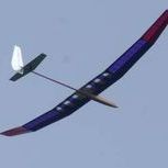
Gary B Posted November 27, 2015 Share Posted November 27, 2015 Wow, the other Bubble Dancer!! I've had the plan (Ron Armstrong) for a while but didn't realise that fuselages had been available. Would be very interested in buying that Mark (and I would build it online here but would have to choose another title!!). Cheers Gary Link to comment Share on other sites More sharing options...
abbof3f Posted November 28, 2015 Share Posted November 28, 2015 Sorry to hi-jack thread again but thought ya might want to see this Link to comment Share on other sites More sharing options...
martynk Posted November 30, 2015 Author Share Posted November 30, 2015 Been a bit of a funny weekend. Weather has been dreadful so no flying, wife has lost her voice so no talking I did manage to lay a footpath in the front garden on Saturday (in the rain), but the rest of the weekend has been spent building. Maybe 20 hours or so.. I wont repeat all the previous images, but all 5 panels now have a lower spar, TE fitted and in one case, the epoxy is still curing. I started to think about the wing tips. I am not sure just how the curves were achieved on the original, but I decided to laminate mine from 1/16" soft balsa with a single 0.007" C/F layer The template was cut from 1/2" builders ply, the laminations are about 3/8" wide, glued with a ix of PVA and Epoxy and left overnight to cure Obviously, still a bit rough but trimmed and glued into place - both tips have been done like this I have also moulded my C/F tail mount assembly The formers were cut from some builders pine. Cling film used as the release agent a little epoxy, fingers crossed and left overnight on top of the shed radiator to cure The boom mounted part The tailplane part Released and released First time I have ever done anything like this. Not quite as difficult or frightening as I thought it would be I managed to wreck the tailplane mount so had to make another (I trimmed it incorrectly) This morning they look like this - I need to finish trimming and sanding them to shape and add the hinges - which with be slightly different than MD method - mainly because I can't quite visualise just what he did. Not the best photo, a little underexposed.. The final big task this weekend was to build the jig for the dihedral angle. I have often thought how useful a hinged board would be. My original plan would be to have a board that folded back on itself, unfortunately to achieve this, the hinge would stick proud into the build area so I had to assemble with a recessed hinge. One of my original boards - 4ft x 1ft with a new 2ft x 1ft extension Recessed hinge To store, it needs locking so the small battens underneath are screwed to both halves. To release, I need to unscrew the upper 2 screws. The cross battens are used to stop the board from bowing. I use Pine boards which will bow unless restrained. To set the jig, I use a 'Bubble level' app on my smartphone Place on the level part of the board and zero, Move to the tilted part and prop up until you get the 10deg tilt At this point a 1/2" ply upright is screwed into the tilted part so it isn't going to move. I need to do 4 joint like this Last night, I assembled the first joint. This is the LH dihedral break - note that I have added 2 additional gussets at the TE junction The joint was well weighed down and left to cure overnight - slow set epoxy used as the adhesive Finally, a shot of the board tilted. Good progress, but still lots to do. More to come. 3 Link to comment Share on other sites More sharing options...
oipigface Posted November 30, 2015 Share Posted November 30, 2015 Quote ....glued with a (m)ix of PVA and Epoxy and left overnight to cure Tell me more about this Martyn. I have never heard of using this mixture before. Pros? Cons? When useful? Link to comment Share on other sites More sharing options...
martynk Posted November 30, 2015 Author Share Posted November 30, 2015 It wasn't very clear was it and TBH I am still playing with the idea. I have used PVA and Cyano many times - that works really well, using PVA for a resilient joint and then tacked in place with Cyano. The moisture in the PVA helps the Cyano to set. The problem here was that you need to assemble the laminations damp. (The alternative way is to simply mould the laminations around a former unglued, let them dry then glue afterwards. I don't get on with that method so well). I also prefer to use epoxy rather than Cyano for the Carbon to balsa joint. Just try smearing the Epoxy onto Damp wood and you will end up with a horrible congealed mess of opaqueness. I am not sure how well this would stick or cure so as well as using PVA in the wood to wood joints, on the Carbon to wood joint, I applied Epoxy to the carbon - a very thin smear - a bonding layer - then rubbed PVA into the adjacent wood laminations (each side) to try and displace as much water as possible. (I had already squeezed it fairly dry anyway). Damp wood expands and the grain starts to lift) The idea was to fill the grain, the PVA would harden first and the Epoxy would then bond (remember its a very thin layer) to the PVA. You don't need much PVA to do this. The result seems to have worked. I have 2 very light and very strong laminated wing tips which do not appear to want to fall apart so I am quite pleased with the result. Time will tell and if they are still in one piece after they have been sanded to shape then I will be very happy. Link to comment Share on other sites More sharing options...
martynk Posted December 2, 2015 Author Share Posted December 2, 2015 Apologies if this is Deja Vu. The hiccup today has meant that I am trying to remember what I typed this morning and possibly more important, not contradict myself. I feel very sorry for Austin BTW, Its a lot of work running a website and one with an advanced forum such as this will have problems. Nice to see that there is a recovery method that seems to work well. More power to your elbow, Austin - thanks Continuing with the wing. As mentioned above, the RH middle and centre panels are on the jig and securely located, the TE joint has been carefully sanded to shape, the joiner blocks are in place and now time to get the middle webs and upper spar in place. Using Epoxy for the wood <> Carbon joins and PVA for the Wood to Wood joints, the spar and webs went together fairly quickly as everything had already been pre-cut and sanded. With all the parts glued up the spar assembly needed to be compressed. The builder on the Aviator Studio Website devised a method using a number of wooden clamps to compress the spar to ensure a good joint. This seems a bit OTT for a one off build and I did consider using my SLEC fuselage jig as this has a number of M5 captive nuts that I could have used. However, I wanted to keep the wing in the jig until the entire spar has glued and cured. My approach was perhaps a little unusual. I bound the spar down using 175lb B-S Sea Ranger Dacron fishing line. This doesn't stretch too much and is very manageable (compared with mono-filament). Avoiding any woodwork - such as the wing ribs and TE, and with one wrap per bay, I gradually increased the tension until I got a healthy twang when I plucked each one. The tension for each pass was adjusted until all the twangs were about the same pitch. When I was happy, I then rolled a length of 8mm dowel under the cord and above the upper spar. This removes the local pressure and spreads the load. You can see that the tension is correct because any excess Epoxy will ooze out of the joints. There shouldn't be much anyway and it may take a few minutes for the tension to take effect. Remove the excess. You can just see the epoxy easing out in this shot in the next bay down. Should be minimal as it is a waste. There is also an extra clamp across the beam bar and joiner blocks to ensure that these joints are solid. Left to dry for 24 hours then I separated the centre panel from the middle panel. I was incredibly relieved when the centre panel joiner slid out smoothly.. Using the same method that I used to cut the centre panel webs above, the webs for the middle panel were cut and sanded to size (3/8" balsa) and the upper spar added and all glued up. One thing that I forgot to mention this morning is that the spars in the middle section tapered from 0.030" > 0.014" (2 pieced - one 12", the other 24") and were glued up last week and left to cure on top of the shed radiator. The assembly and binding process was repeated for the middle panel. There is a couple of gotchas that are quite easy to overlook. On the joint between tip and middle panel, the spars (upper and lower) are linked by short lengths of 0.007" carbon. This shot shows the lower pieces in place, a bit messy but that will be covered by the break ribs and adjacent webs and excess removed before it gets on the plan. The double rib in place. You can also see the other bit that can be overlooked. There is a short length of 0.007" carbon used as a compression link. The tip is protruding just out of the ribs. I may have made a mistake here. The plan is not very clear, but it seems to me that it would have been better if I had extended the webs so they butted against each other and removed a short section of rib. Too late now.. With the binding and dowel in place on the middle panel and the tip panel sat patiently waiting for its turn. Finally for last night, left to dry.. This evening, the tip panel has also had the 1/4" webs and upper spar added. This was little more complex as the last part of the upper spar curved slightly into the tip. This meant that it was trying to force the spar off the web. To hold it all down, additional cross clamps were used in adjacent to the binding. Photo to follow, this was tomorrows update And who said bondage was dead? More to come. Link to comment Share on other sites More sharing options...
martynk Posted December 7, 2015 Author Share Posted December 7, 2015 Trying to remember where I was up to.. Continuing from above the tip webs and spar caps have been added and clamped down. It may a little excessive, but the cap curved downward which was making the spar lift further down the panel. This was the method of curing it. When I did the other wing tip, I simply added a little packing between the dowel and the laminated tip - that was much easier. While waiting for glue to dry, I moved over to my main building board and started work on the Spoiler slot in the upper side of the centre panel. The plan shows that the lateral spar assemblies should be assembled from lots of single pieces filling the gap between the ribs. I chose to cut slots in the ribs then drop a full length 'spar' into the slot. A technique shown to me by a fellow forumite here about 43 years ago! Some things you never forget.. The verticals behind the spar sit proud by 1/16" and line up with the wing ribs (after sanding). They delimit the trailing edge of the spoiler The front edge of the spoiler has a section of triangle that the spoiler sits against. To the rear of that a second 'spar' has been added - also be cutting a suitable slot in the ribs. The film covering uses these spars as adhesion points. The sharp edges were removed from the Carbon spar caps by gently filing - using a fine triangle file between the ribs. That didn't take long compared with the binding. What seems to have taken an age has been the Kevlar binding. I cant pretend that is the tidiest thing you will ever see, but the main spar has been bound with 2 strand Kevlar thread that I bought from Mike Woodhouse about 30 years ago Quite fiddly trying to keep the winding tight and linear. At the inner dihedral breaks - where the 10mm joiner is boxed in, I have added 0.007" Carbon caps (using epoxy) along the sides to hopefully add a little extra strength. You can see from the photo above that there isn't much spare material. This was then multiple bound in bunches to really hold it together. The Kevlar was held in place with small tacks of Cyano. I don't want to use too much as the Kevlar will be wetted thoroughly when the binding was completed. (Before they were tidied up). While all this was going on the rear joiner was added into the trailing edge. 3mm Carbon rod fitted into the inside of a plastic (PTFE?) drinking straw and with the inner panel and middle panel back in the jig this was glued up and left to cure for 24 hours. A very snug fit. Lightly sand the tube to provide a good keying surface. While that panel was drying, I fitted the rear support 'spar' on the other panel. This comprises of lots of individual pieces. In this case, I chose not to cut the slots in the ribs but followed the instructions on the plan. I am still unclear why slots were not cut. With laser cut parts you are guaranteed a good fit and it appears to me that a contiguous spar makes better sense. Not much done over the weekend, an unfamiliar activity called 'shopping' (I think that is how it is spelt) caused an unwelcome distraction but I still managed about 10 hours due to insomnia striking again. Tonight's activity involved 'wetting' the Kevlar and putting the panels safe to dry. Used Finishing Epoxy for this applied with a small paintbrush. (20 for 99p from Rymans). This is one bay out from centre and has double windings of Kevlar - drops down to a single winding up to the bay adjacent to the joiner box bay. and This is the centre rib around the Beam Bar. As recommended on the plan this has many windings of Kevlar thread. The windings have been tidied up as you can see. Now, I have a problem. Following the build sequence, I will be adding the D box sheeting fairly soon However, I don't understand this. At the rear of the lower sheeting - where it butts up against the spar assembly, there should be a 0.015" step. I have dry fitted a piece of 1/16" sheet and there is a step there but I cant see the point of it. Anyone have any suggestions what its for? More to come Link to comment Share on other sites More sharing options...
Ribs Posted December 7, 2015 Share Posted December 7, 2015 Hi Martin, Beneath the spar on the bottom surface, a 0.015" shim is used (mylar) while the wing is buikt up. Once kevlar wrap is done, bottom sheet can be added along witg false TE. Triangle fillets, complete the D box, with the top sheet wrapping over and beyond the top spar. This leaves a small gap under, where the shim was. This is then filled with a strip, the voids around the kevlar filled with a thick epoxy/silica mix. When cured, the strip is sanded back to the section profile and flush with the bottom LE sheeting. Hope that helps, Cheers, Chris 1 Link to comment Share on other sites More sharing options...
Ribs Posted December 7, 2015 Share Posted December 7, 2015 Corrections! "Built up" "False LE" not TE Clumsy fingers on phone/tapatalk sorry! Link to comment Share on other sites More sharing options...
martynk Posted December 8, 2015 Author Share Posted December 8, 2015 Thanks Chris I saw that on the Aviator Studio website but its not shown on my plan. The bit that puzzled me was the .0.15" where 1/32" balsa is twice that thickness (or thereabouts). That does make sense thouugh Cheers Link to comment Share on other sites More sharing options...
oipigface Posted December 8, 2015 Share Posted December 8, 2015 Martyn, Have you got any idea how you are doing for weight so far? Link to comment Share on other sites More sharing options...
martynk Posted December 8, 2015 Author Share Posted December 8, 2015 Not yet. I have not been keeping such a close eye on the wing weight as there is very little I can do about it once the materials have been selected. The outer panels feel very light, the inner, less so. I am waiting for the resin to cure from last night. The outer panels have cured perfectly, the inner is still very tacky so I have just redone it and brought it in the house while the present Mrs K is out for the afternoon. Resting on a warm (the warm radiator!) radiator with a piece of newspaper preventing the radiator from gluing itself to the wing again. Must remember to hide it before 6:00pm Link to comment Share on other sites More sharing options...
oipigface Posted December 8, 2015 Share Posted December 8, 2015 22 minutes ago, martynk said: Resting on a warm (the warm radiator!) radiator with a piece of newspaper preventing the radiator from gluing itself to the wing again. The newspaper can glue itself instead! Link to comment Share on other sites More sharing options...
martynk Posted December 8, 2015 Author Share Posted December 8, 2015 LOL. That's OK providing the wing doesn't get damaged and I can absolve myself of any fault in that matter. Got to get the priorities right.. Link to comment Share on other sites More sharing options...
martynk Posted December 8, 2015 Author Share Posted December 8, 2015 A bit of progress this evening. The present Mrs K rang me to say she was staying in Manchester for another 4 hours so I have had a very good evening session today. First a couple of shots I missed earlier The carbon spars have been inlaid into the wing tip Lower Upper - terminated at the laminated carbon strip. The resin looks a bit globular, It's nowhere near as bad as that, just specular highlights making it look worse. <honest> The laminations are holding up well, no sign of de-lamination yet. The resin on the centre panel bindings has cured enough to start work on the D box. My initial plan was to get the upper sheeting in, then the lower triangle and then the lower D box sheet. Then I had a sensible thought. The lower sheet went on first: No triangle You can see the test fit of the 1/32" cap strip that sits over the lower carbon cap. Not glued yet While the PVA was drying for the lower sheet, a quick trip down to B&Q for some more Gorilla Glue (and more slow setting epoxy). Gorilla Glue is lighter than an epoxy/silica mix and probably more effective as an adhesive in this context. No one is going to pretend that the 1/32" cap is structural - its purely cosmetic. A very thin smear of Gorilla Glue on the balsa cap and then compressed it all into shape. Two benefits for this approach. The Gorilla Glue will swell into the gaps where the Kevlar thread is wrapped around the spar.. The other benefit is that the panel is held absolutely flat while the glue dries and cannot be forced apart. So while the Glue dries, I can now fit the triangle pieces that sit at the front of the spar to support the lower D box sheet Using Gorilla Glue for the carbon junction and PVA for the junction against the lower sheet Now watch carefully for an hour or so. As the Gorilla Glue starts to swell it will ooze out the gap and will run onto the building board if you are not careful. Keep removing the excess and when the expansion flow has finished but while the glue is still tacky remove the panel. Leave it too long and you may end up with a very odd wing shaped building board that you don't really want. With the wing flipped over, you can then sand the excess 1/64" off It doesn't take much sanding to get to the Kevlar threads. Time to stop sanding There is one area that I am unhappy with on this section. Towards the dihedral break, one of the ribs hasnt aligned correctly and had to be packed. I didnt quite get it right and it will need a little filler The final job tonight and definitely not part of the original was to start adding the 0.007" carbon cap strips over the ribs. I know that MD knows his stuff but I was just thinking that with the main spar being so rigid, I was wondering just what would be happening to the TE during a winch launch. These caps may add a few extra grams but will add a lot of strength (I hope). These are the lower ones.. A couple of other jobs. The lower side of the beam bar has been boxed in and the sheet blended into the rib. This is in the fuselage so out of sight but it looks better than the carbon beam. The ragged edges will be tidied before the wing gets covered Finally, the LE braces have been added. Interestingly, they are shown on drawing (in plan view) but not another. I have no idea what the thickness should be so went for 1/4" sheet - light balsa. A bit dusty after sanding to fit. And..... I forgot to weigh it.. <sorry> More to come. Link to comment Share on other sites More sharing options...
oipigface Posted December 9, 2015 Share Posted December 9, 2015 Martyn, I think there are several varieties of plastic sheet that Gorilla Glue doesn't adhere to. Mylar is one of them (I think). You might consider using one of these to keep your building board and wing as separate items instead of watching the glue dry. John 1 Link to comment Share on other sites More sharing options...
martynk Posted December 9, 2015 Author Share Posted December 9, 2015 Thanks John TBH, I haven't found anything it doesn't stick to (or make a mess of). I normally use cling film as a separator but that is a nightmare as it just gets ripped to shreds and you end up trying to peel it off the airframe in small pieces. I'll try Mylar - I need to get some anyway for my experiments in Vac bagging. Link to comment Share on other sites More sharing options...
martynk Posted December 13, 2015 Author Share Posted December 13, 2015 A bit more progress. The bottom sheeting has been completed and the balsa caps to the ply caps has been added and then sanded back flush So - making a start on the upper sheeting. Now at the risk of teaching my granny etc the point that you add the upper sheet and completed the D box, you are effectively locking in any warps that you may intentionally or unintentionally add. They can be moved, but it will be a chore. This is the middle RH panel and needs 0.75 degrees washout. Using small angle approximation (Tan0.75 x 8" chord) = 3/32" packing (that was convenient). You can see the packing at the Dihedral break and the clamps holding the wing in place while the glue sets. PVA for the wood to wood and GG for the bong between the carbon and the upper D box sheeting Another shot with the British Standard Aeromodeller's shed weight holding the TE securely in place. Additional packing pieces (of progressively lesser thickness) are added with the other end of the panel flat on the board. Adding the upper sheeting to the tip panel. Note the panel is back on the dihedral jig. This panel is flat, but still inclined with 0.75 degrees washout in relation to the root break, so the entire TE needs packing up by 3/32".I have to use pins here to hold the sheet to the LE as there is insufficient space to use clamps.You can also see that I have added 0.007" carbon cap strips (upper and lower) - a marginal increase in weight but worthwhile IMHO. And another shot. The caps cover the rib/TE junction, are glued with thin cyano. Note the push pin doesn't go through the wood, the plastic bit is pushed down on the TE. LE - another minor change. The plan says 1/8" hard - I didn't have any hard wood so settled for 2 laminations of 1/16" balsa and spruce. I dont think this will add any significant weight as most of the spruce is sanded away The bad news - I need a bigger shed. I couldn't resist doing a dry assembly this afternoon. Quite pleased with the wing so far.. A close-up of the wing tip - the LE still needs trimming back but it overlaps the laminations adding a little extra resilience Finally, tonight I have capped the break ribs with a single layer of carbon - less than 3g of resin used for this . There will also be carbon gussets holding the rear joiner in place. The carbon cloth is impregnated and a piece of cling film carefully added then the panels are clamped together until the resin cures.Excess cloth will be trimmed and sanded away. --- Now the depressing bit. I weighed the other outer panel this evening and it looks like it going to be about 40g overweight (each panel). I think that the main culprit has probably been was the selection of wood in the D boxes which was denser than specified. The reason, I cant find decent lightweight wood that doesn't crumble at the first sign of stress. I am not too worried though. it just means that I will have to carry less ballast. (Be positive) and the model will fly a bit faster I am now starting to think about a winch system and I am about ready to start another "Dumb Question" thread - hope you will forgive me for this.. More to come 3 Link to comment Share on other sites More sharing options...
Recommended Posts
Create an account or sign in to comment
You need to be a member in order to leave a comment
Create an account
Sign up for a new account in our community. It's easy!
Register a new accountSign in
Already have an account? Sign in here.
Sign In Now