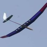
martynk Posted March 17, 2016 Share Posted March 17, 2016 Following on from my earlier post in the Electric Section, I herewith present my humble offering for an Electric 100S. Any similarity to a Bubble Dancer - albeit this is smaller - is entirely intentional. The wing construction is very similar- the biggest difference is the straight taper (from 9" to 6" chord) and possibly the one thing that I feel *really* uncomfortable about - the V dihedral The main reason for this this is that it will simplify construction and - what is becoming a big issue for me now - storage. Following Jef's suggestion, I have moved the spoilers out to about 1/3 span. I had noticed on the BD the lack of elevator authority when the barn door spoilers were raised so he may have a valid point. Wing section is AG35 root tapering to AG37 at the tip with a similar wing construction - laminated carbon spar caps plus full width balsa web/spars.However, the amount of carbon has been reduced to 10mm x 1mm at the root > 10mm x 0.5mm at the tip (Top and Bottom). Projected wing span = 97" Still not sure on the power train but I have opted for a 1500 3S, 40A ESC and a cheapo 2837 950kV Outrunner driving a 12x6 folder. eCalc didnt blow a fuse when I suggested this so I hope it will be OK. Target weight - ho ho ho - 1.25-1.5 kG Thoughts please before I commit the parts to my laser cutter. Cheshire Cat 100S-E Plan.pdf 3 Link to comment Share on other sites More sharing options...
Jef Ott Posted March 18, 2016 Share Posted March 18, 2016 Firstly, I am not a designer (so please take my comments with a pinch of salt), but that dihedral angle looks too much to me, I would have thought that 5 or 6 degrees each side would have been adequate, for a 100" span model with straight V dihedral. Perhaps you can verify this by looking at other designs? Is it really in the order of 8" under each tip? Working from observations made during the previous century, so forgive me if my memory is corrupted, but... * Smaller models tend to need more dihedral angle than larger ones (the angle drawn looks about right for a mini-DLG). * Too much dihedral will lead to dutch rolling, and won't look nice. * The spoilers normally pivot from the fattest part of the wing section (it looks like the spoiler on the drawing is a little further aft), not saying this is wrong, just unusual. Perhaps some of our more experienced members could comment, before you commit to paper/wood. Thought I should speak up, despite my thoughts being based on experienced observations rather than technical engineering fact. 1 Link to comment Share on other sites More sharing options...
Jef Ott Posted March 18, 2016 Share Posted March 18, 2016 On the positive side... Target weight is sensible, drive train is sensible (I would go for a bigger ESC though, 50A), I would leave enough room for a 2200mAh LiPo battery and an AA NiMH Rx pack. Wing shape is sensible. Tail sizes are sensible, but the boom looks at least 3" too short to me. This is based on 60" span models that I dabbled with and found that the minimum distance between the tailplane and the wing should be one third of the span. It might be an idea to add 2" to the nose too, to give yourself room to manouvre things to achieve the best CG. Why the change of heart from MH to AG? Not that I would notice any difference! 1 Link to comment Share on other sites More sharing options...
martynk Posted March 18, 2016 Author Share Posted March 18, 2016 Thanks for the comments Jeff - really appreciated. I guessed that everyone was either laughing out loud or silently agreeing with my approach.. I am working on Mark Drela's design guide which recommends 10 degrees EDA (Effective Dihedral Angle). For a V dihedral that equates to the real dihedral angle. I agree it looks a lot though... EDA Discussion here http://www.rcgroups.com/forums/showthread.php?t=1428410 I have put the spoilers behind the LE sheeting - same as the the BD - maybe that is why they are so big. I get a very steep pitch down when I deploy them with very little elevator authority when I try and correct that...However, it crashes ....s.l.o.w.l.y... Horizontal Tail Volume Vh - I have just calculated that and it was in the stable region but slightly less that MD recommends. I have extended the moment by 4" to bring it up to 0.4. Very well spotted Vertical Tail volume Vv is also very slightly down (0.027) from MD recommendations. I was considering putting a small under fin under the tailplane. That will compensate and bring the Vv up to about 0.03 There is plenty of room in the fuselage. I am trying to give me enough flexibility to move the LiPo backwards/forwards to adjust the CG. Servos will fit behind the ballast with the height limiter/cut out. Is it normal practice to carry a separate receiver battery? That surprises me. Wing section MH to AG - mainly because I had trouble spelling AG when I typed out my plan Really appreciate your comments and thoughts.. I am about to start on the tailplane and fin this weekend and an order has gone to hyperflight for the carbon bits - which wasn't cheap. My next big problem is how do I join the wings? Tempted with a single 6G Piano wire joiner but again - would welcome thoughts on this Link to comment Share on other sites More sharing options...
martynk Posted March 18, 2016 Author Share Posted March 18, 2016 To finish off, Blaine Rawdons Parameter = 5.7 which is lightly higher than MD suggests but is Spirally stable Link to comment Share on other sites More sharing options...
Jef Ott Posted March 18, 2016 Share Posted March 18, 2016 2 hours ago, martynk said: There is plenty of room in the fuselage... Is it normal practice to carry a separate receiver battery? That surprises me. Hi Martyn. No it is not standard practise. It is my standard practise though. I have seen many models go in, and seen some very lucky escapes, where the solder has melted in one of the LiPo to ESC leads. And yes, I have even seen the solder melt on a connector of one of my models (I buy second-hand a lot) and the separate NiMH (£5) saved my model from almost certain disaster, in that instance. Had the previous owner carried on using it for 6 more flights he would not have been so lucky, as he had been relying on the LiPo to power his Rx. Since the mid-nineties, when I started flying rc gliders, I have heard of only one case of an AA Ni-XX battery failing and causing a thermal soarer to crash (other than through sheer old age with 10yr old+ cells ). If you don't use a separate Rx pack, I would even go as far as to suggest, if you buy a second-hand ESC or LiPo battery, you should cut off the plugs and sockets on the ESC supply side and solder on new ones, as it is difficult to assess the quality of the soldering without actually doing it yourself! 2 hours ago, martynk said: I am working on Mark Drela's design guide which recommends 10 degrees EDA (Effective Dihedral Angle). For a V dihedral that equates to the real dihedral angle. I agree it looks a lot though... Does that make allowances for wingspan? A lot of Drela's work is relevant to DLGs (where spans are considerably smaller), I agree with most of his recommendations for DLGs. It would be a good idea to check out plans for other V dihedral models of a similar span before you make a decision. It is a lot easier to add dihedral afterwards (if flight tests prove that more is necessary), than to take it away, if it is too great! 2 hours ago, martynk said: My next big problem is how do I join the wings? Tempted with a single 6G Piano wire joiner but again - would welcome thoughts on this I have a pair of friends that have done a lot of winch launching with John Stevens Eliminator 100"S models, they have moved away from using the standard 6SWG and 1/4" joiners (one of each, in each model), and now use a larger main joiner, which withstands the fierce launch loads that their modified carbon reinforced spar system allows. Obviously you don't need that kind of strength, but I personally don't think the single 6G (4.877mm diameter) joiner would be strong enough to do the job. The only electric model in my collection that has a 2-piece wing, is the Reichard Rapid. This is a 15yr old plane. It has withstood many hundreds of my landings (see pic below)... It deploys an 8mm main joiner and a 3mm location joiner (I just took my micrometer into the attic to make sure of the measurements). When I wanted to increase the dihedral angle on this (aileron) model (to suit my lazy flying style), I was able to achieve my goal, other than that, the angle has remained set (without flight/landing stresses affecting it). I would recommend the same dimensions for your joiner, as the Rapid gets a harder life, but has a smaller span (86"). Picture courtesy of Josie Cordwell / Jason Burns. 1 Link to comment Share on other sites More sharing options...
martynk Posted March 18, 2016 Author Share Posted March 18, 2016 Thanks Jef Good sound advice - appreciated. One of the options for the joiner is to use an 8mm Carbon Rod - which will be strong enough. The challenge will be bending it to suit the V Dihedral - I have a cunning plan though. The dihedral saga. 10 degrees is quoted on several sources. Its also used to calculate Blaine Rawdons Parameter. This is a tricky one. I have been trying to find plans for V dihedral RE models but they are very sparse. However, the EDA for Bubble Dancer is 12.4 degrees. I think I am safe - I guess flight tests will be the order of the day.. The recommendation for a DLG is slightly different as you pointed out. It should be easy to change if its wildly wrong. It will just need a new joiner and the root redoing to remove the gap. Nice photo - were you aiming for the White Flag? Link to comment Share on other sites More sharing options...
Jef Ott Posted March 18, 2016 Share Posted March 18, 2016 2 hours ago, martynk said: To finish off, Blaine Rawdons Parameter = 5.7 which is lightly higher than MD suggests but is Spirally stable I have never heard of Blaine Rawdons Parameter, so the number means nothing to me. Here are my thoughts... If the Rudder is not big enough, it is not too demanding a job to make another with increased area. If the area of the fin and rudder combined is too large, then you will get spiral instability. Without flying the model you will not know whether the combined area is perfect or not. My definition of 'perfect' is this... The model will fly itself without offset rudder trim in a straight line, when there is no thermal activity, and will maintain a turn in either direction, when slight up elevator is applied. When thermal activity is present, if you are centred correctly, some rudder input (into the thermal) will be necessary. 7 minutes ago, martynk said: Nice photo - were you aiming for the White Flag? Err... no!.... I was aiming at the red tape, which the nose is planted in (hence the YES! grin on Ray Gadenne, the timekeeper's, face). Link to comment Share on other sites More sharing options...
martynk Posted March 18, 2016 Author Share Posted March 18, 2016 Hi Jef Here is the spreadsheet I have used to calculate EDA plus an extra page I have added for Vh and Vv and B calculations. The article by MD is here: http://www.rcsoaringdigest.com/pdfs/RCSD-2004/RCSD-2004-08.pdf Pages 13-15 If you have excel - have a play with it - its quite reassuring I hadn't spotted the Red Tape - blended with the Red wing..I can see why the timekeeper was happy. Nice one.. Vh Vv eda1.xlsx 1 Link to comment Share on other sites More sharing options...
Jef Ott Posted March 18, 2016 Share Posted March 18, 2016 Martyn, Thanks for the link. I have started reading through it, but I find it very difficult to make myself continue reading articles like this, once I have found there are a couple of glaring typos. This is part of my personality and I wish I wasn't like it. I wish I could be more tolerant. It is probably very good if you can bother with deciphering the typos, and the maths will probably provide a range of values that back up what can be found through determination and endless hours of enjoying oneself with real models in the air... The theory gives you a ball-park starting point, a range of workable values, which might save some re-work. Trimming the design to your own definition of perfection is always going to be down to personal taste, however, and there is not a "one size fits all" best glider design. If there was, it would be boring and we would all be flying that design already. Regarding the joiner, if it were me, I would build it with a nice bendy metal one... then I would fly the thing lots, making notes on the handling at differences of 5mm dihedral at the tips (you have to forget about the degrees and just use millimetres sometimes), until my favourite amount of dihedral emerged. (Oh hang on a minute, that is what I do.) Then and only then, if the desire to have that angle permanently set in carbon still existed, would I make one in carbon. (But I know it would never get to that!) If you build the model with as much dihedral as you are told to, by MD, it will fly. Go for it! 1 Link to comment Share on other sites More sharing options...
Jef Ott Posted March 18, 2016 Share Posted March 18, 2016 Martyn, Please can you add the modified drawing - including the dimensions drawn onto it, required in the spreadsheet? Many thanks, Link to comment Share on other sites More sharing options...
martynk Posted March 18, 2016 Author Share Posted March 18, 2016 Here you are - v2 of the plan. I haven't bothered with the colour version this time Best wishes Cheshire Cat 100S-E Plan-v2.pdf 2 Link to comment Share on other sites More sharing options...
Jef Ott Posted March 19, 2016 Share Posted March 19, 2016 Looking good now Martyn. All the dimensions make sense to me now. I would still make the nose 2" longer, to give more flexibility on locating the best CG without the need for any lead, but your lightweight tail-feather building skills are probably better than mine. The other things I would definitely urge you to consider, would be to angle the bottom of the rudder up away from the ground, and put a small skid under the fin, to protect your servo in the event of an ungainly arrival. Good luck with the Cheshire Cat build! Link to comment Share on other sites More sharing options...
Jef Ott Posted March 19, 2016 Share Posted March 19, 2016 (edited) Just one more observation, Martyn, In reading the EDA explanation, it becomes clear that there are completely opposite viewpoints between the author's findings and my own observations. The EDA explanation author believes that smaller models require less dihedral than larger models, and I have observed that smaller models require greater dihedral angles than larger ones. Fascinating stuff! This explains the gulf between our views regarding the required dihedral for your design. So whereas the spreadsheet allows the DLG a CL of 0.6 (which I agree with) I would place your larger model in the region of CL 0.5. When this happens, hey presto, it shows stability with the dihedral at 6 degrees, the corrected values entered, and a less draggy, smaller Vertical Tail area, more in line with Brian Austin's successful Trilogy 6 design, which I cut my competition teeth on. Thanks for the enlightenment. Edited March 19, 2016 by Guest Trying to show more reason behind my views. Edited while the next reply was added. 1 Link to comment Share on other sites More sharing options...
Committee Member PeteMitchell Posted March 19, 2016 Committee Member Share Posted March 19, 2016 Try using the calc programme on this site. I have found it very accurate in its predictions, once you have learned how to drive it. http://www.tailwindgliders.com/files.html 1 Link to comment Share on other sites More sharing options...
martynk Posted March 19, 2016 Author Share Posted March 19, 2016 Hi Pete I have seen this app but not really spent too much time with it. I'll take a closer look. Jef - I would have thought a larger Glider would have a higher CL (than a DLG) as the wing is operating at a much greater efficiency. I'll have a look using Profili later. At the moment, I am toying with a 5 panel wing - however, if I did that it would look even more like a BD Jury is out on that at the moment. I reduced he nose length slightly as my pods tend to be rather heavy-compared with a glass or Carbon commercially produced offering. haven't started yet. Been doing field maintenance today. Maybe tomorrow evening Best wishes 1 Link to comment Share on other sites More sharing options...
martynk Posted March 21, 2016 Author Share Posted March 21, 2016 Still dabbling with the design and also reading Martin Simons excellent Aerodynamics book (again). MS states that Dihedral should form an elliptical shape - or as near as can be reasonably achieved. With this in mind, I have redrawn the wing with a 5 panel wing - joined in the centre and through the fuselage. This stretched the wing span be almost 50mm and brings the projected span nearer to 100" (Sorry for the mix in units). I have to admit that it looks better and trying to keep the EDA at about 10 degrees but using sensible numbers. Still somewhat less than the BD though So - attached the EDA Calc, a revised colour image and the PDF. Cheshire Cat Poly Wing Plan-v3.pdf I have also added a small sub-fin - 10 square inches but not massively effective as its too shallow - however it has a secondary function of protecting the rear end. A bundle of carbon bits arrived fro Hyperflight today but I still haven't got round to gluing wood together yet..Working away for a couple of days. As usual, your thoughts are very welcome. More to come 1 Link to comment Share on other sites More sharing options...
Jef Ott Posted March 22, 2016 Share Posted March 22, 2016 Martyn. You have said that you have a problem with hangar space, so one does have to ask the question, why not just build an electric fuselage for your BD wing (almost no extra storage space required). It must be something that you have been considering. The compliment to that would be a 100" full house wing, for windy weather, with a 500W motor, 60A ESC and a vee-tail. Job done then, one big electric floater for lazy days, one easy to fly in a breeze for fun and competing. You're as bad as me! Link to comment Share on other sites More sharing options...
Gary B Posted March 22, 2016 Share Posted March 22, 2016 Out of interest the Chris Foss Centi-Phase is a 'V' dihedral 100" RES design. It has 4 degrees under each panel (total of 8) and flies very nicely. I use the Sailplane Calc programme, some of the parameters (like spiral stability) would indicate that it wouldn't fly well at all, I've seen this with other glider designs that I've inputted the numbers. The programme is usually dead on for wing loading, CG neutral points and tailplane sizing. A three-piece wing is very strong and can have lighter tip joiners (granted there are two!). GB 1 Link to comment Share on other sites More sharing options...
Gary B Posted March 22, 2016 Share Posted March 22, 2016 A rule of thumb that I can't remember where it came from is one degree dihedral per foot of span, which works out at 8.3 for the Centi-Phase. I have a Flair Sunrise, straight inner panels, dihedralled tip panels. It will lock into a turn to the point I think I've had radio failure but can clearly see the rudder hard over out of the turn trying to right it! I also have the Albatross (its successor), quite a lot more dihedral on the tips. Link to comment Share on other sites More sharing options...
Recommended Posts
Create an account or sign in to comment
You need to be a member in order to leave a comment
Create an account
Sign up for a new account in our community. It's easy!
Register a new accountSign in
Already have an account? Sign in here.
Sign In Now